A free body diagram is a pictorial representation often used by physicists to show all contact and non-contact forces acting on the given free body. Drawing such a diagram can aid physicists attempting to solve for the kinematics of a problem. Doing so can make it easier to understand the forces, and moments, in relation to one another and suggest to the physicist the proper concepts to apply in order to find the solution to a problem.
The diagrams are also used as a conceptual device by engineers, to help identify the internal forces, (for example shear forces and bending moments in beams), which are developed within structures.
Making free body diagrams involves drawing vectors, representing the different forces acting on a given object. The vectors are meant to show the direction and magnitude of the various forces.
It is common practice to add to the diagram a vector which depicts the total force (or net force) acting on the free body. This vector is generally shown independent of the body. This is helpful in problem solving because it shows the total effect that the forces have on the body.
Procedure
The process customarily begins by drawing the mass in question, and sometimes a few of the objects with which that mass interacts. This visual aid is not strictly necessary, and may be distracting, since all vectors are drawn as coming from a single point within the mass. Also, in a given free body diagram, only the forces acting on a single object are considered. Next, a careful accounting of all appropriate forces acting on the mass is made. This may include forces such as friction, gravity, the normal force, drag, or plain old contact force due to pushing. When in a non-inertial reference frame, fictitious forces may be appropriate. Once this is done, draw each of these forces as vectors (arrows), with the tail of every vector at the same place in the center of the mass. Each vector should point in the direction of the force it represents, and be labeled with the magnitude of the same force. Many people prefer to draw the forces pointing towards or away from the point of application on the mass rather than placing the tail always at the center. This is done usually to indicate that the force also results in a torque on the mass.
At this stage, a coordinate system is usually drawn onto the diagram, according to convenience. The x direction might be chosen to point down the ramp in an inclined plane problem, for example. This allows the physicist to write down Newton's second law for the several axes, and so solve for the acceleration of the mass in the x and y directions separately.
It must be stressed that only those forces acting on the mass in question are drawn on a free body diagram. Forces which that mass causes on another object are never included. For example, if a ball rests on a table, the ball applies a force on the table, and the table applies a force on the ball. But if one is drawing a FBD for the ball, then only the force that the table causes on the ball is included.
Example

A simple free body diagram is of an object sitting at rest on a surface. The free body diagram on the right (Image 1) illustrates this. It has the object’s weight pointing straight down and the object’s normal force pointing straight up. Below are more extensive explanations of weight and normal force.
- Weight (W), always acts downwards on the centre of mass of an object.
- The normal force (N), is always directed perpendicular to the plane of contact between two objects.
Consider the inclined plane of image 2. Here the same two forces apply, however we have also decomposed the weight vector into two other components, one parallel with the inclined plane and the other perpendicular. The magnitudes of these two components are Wcosθ and Wsinθ
where:
- W = whole weight
- θ = the angle the incline creates with the horizontal
Image 3 shows exactly the same situation except θ is defined to be the inclined plane's angle with the vertical. We will use image 2 for the rest of this article. The additional force found in image 2 but not image 1 is friction.
- Friction (f) has magnitude proportional to the normal force, and direction opposite the direction of motion. The constant of proportionality is called the coefficient of kinetic friction. Problems where the mass has no velocity can still have static friction, which has whatever direction is necessary to maintain equilibrium.
Notice that this choice of decomposition is useful in a coordinate system where we choose the positive x direction to point down the inclined plane and y perpendicular to the plane, upwards. In this coordinate system, there are exactly two forces in each direction. Newton's second law for this situation can be written as
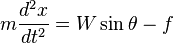

To solve this problem, we note three facts. First, f = μN as discussed before. Secondly, we confine the mass to the surface of the inclined plane, so that the mass has no velocity in the y direction and the second equation becomes N = Wcosθ since d2y / dt2 = 0. Finally, W=mg where m is the mass's mass and g is the acceleration due to gravity. Putting all these things together, the first equation becomes

implies
 .
.
This ordinary differential equation can be solved using the usual methods. If we call the initial position x0 and the initial velocity v0 the solution is
 .
.
Remember that this solution is for the peculiar coordinate system we have chosen, and so x represents the distance that the mass is from the top of the inclined plane. One should also use some caution about the application of friction in this case. If we set θ=0 so that the inclined plane is horizontal, v0 = 0 and x0 = 0, this equation becomes x(t) = − gμt2 / 2, which seems to imply that a mass placed on a horizontal plane will spontaneously move "backwards". This of course is not the case since kinetic friction does not apply to the stationary mass.
No comments:
Post a Comment